Reading circuit diagrams and calculating values
R is resistance in ohms (Ω), V is voltage in volts, and I is current in amperes. Subscript t means total. A node is a continuous wire connection. The source and wire resistance are ideal unless stated otherwise.
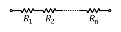
- SeriesRₜ = R₁ + R₂ + … + Rₙ
- Parallel1/Rₜ = 1/R₁ + 1/R₂ + … + 1/Rₙ
- I = V/R
- Unloaded dividerVout = Vin × R₂/(R₁ + R₂)
- 1Trace the nodes and current paths before choosing a formula. A single path is series; branches between the same two nodes are parallel.
- 2Read every component label and the reference point for the voltage. In the divider diagram, Vout is measured from the junction to ground, across R₂.
- 3Replace a loaded lower divider leg with its parallel equivalent before using the divider formula.
- 4Check your result: series resistance exceeds each component; parallel resistance is below the smallest branch. Loop voltage drops and node currents must balance.
A 24 V unloaded divider has R₁ = 3 kΩ and R₂ = 1 kΩ. Vout = 24 × 1/(3 + 1) = 6 V. Independent check: I = 24/4000 = 6 mA. The upper resistor drops 18 V and the lower resistor drops 6 V. Together they account for the full 24 V.
- Treating every resistor drawn beside another as a series connection; follow the wires.
- Using the voltage across R₁ when the output is actually measured across R₂.
- Ignoring a connected load or assuming an open parallel branch stops current in every branch.
Pass Your Red Seal’s lessons and practice are independent study material. Source: OpenStax: resistors in series and parallel, Resistors in series — illustration and licence, Resistors in parallel — illustration and licence, Voltage divider — illustration and licence
In this diagram, n = 3: Rₙ is R₃ and there are exactly three resistors. R₁ = 100 Ω, R₂ = 220 Ω and R₃ = 330 Ω. What resistance is measured between the two terminals?
This topic
Mixed practice
Every math topicKeys this topic uses
- ()Works the part in brackets first
- ALPHA=Types ANS, the last answer